Quantcast
Channel: The ever-expanding world of sigrok blogs
Viewing all 213 articles
Browse latest View live

About fx2lafw

$
0
0

At the end of May we released libsigrok 0.1.1. It had various fixes and improvements, but the main reason we released it was to get a release out the door before merging in the work on analog data I’d been doing in another branch.

But there was one major feature in that release which I think deserves a bit more attention. It was the first time we’ve included a driver that communicates with a device which runs firmware we ALSO wrote. This firmware is called fx2lafw, and I think it’s absolutely fantastic.

The all singing, all dancing FX2

Some of the first generation of inexpensive logic analyzers, i.e. within reach for non-megacorporation budgets, were the CWAV USBee SX and the Saleae Logic. That is to say, they’re under $200. But when you look at what’s inside, as we inevitably do, it becomes apparent that there’s really very little there. Essentially, these boards are based on a Cypress EZ-USB FX2LP chip — the FX2, for short — and a small number of components to support it. The FX2 is a generic USB interface chip, based around an 8-bit 8051 microcontroller core. It runs quite slowly, nowhere near enough to keep up with a modern high-speed USB bus. But it has some built-in peripherals which allow it do fully automated transfers from GPIO pins to the USB bus, without ever touching the 8051 core. You basically tell it which pins to sample, and which USB endpoint to send the results to, and off it goes — leaving the CPU core idle. This feature is intended for transferring data from external devices, such as hard disks, onto a USB bus.
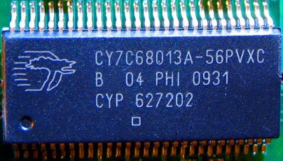


A Cypress FX2 chip
 
But of course that data doesn’t have to come from a device that’s getting clocked to send data to the FX2. It takes whatever appears on the digital I/O pins, which is what a logic analyzer does. So this can be used as a simple single-chip logic analyzer. There’s a bit more to a full product than that, of course — you have to provide some sort of analog frontend, probes, a USB connector, and an enclosure. You’d also have to invest in a website/store, arrange manufacturing, and provide support. But you could sell it without all of that if you really wanted to provide something cheap that will mostly work. Enter the Chinese clones.
 
If you pare it down to its bare essentials, the FX2 needs an 24MHz oscillator, a small EEPROM chip, a USB connector and a few passives. Connect your own probes to broken-out GPIO pins, and you have a basic logic analyzer. So that’s what happened: various FX2 boards started showing up on Taobao, Alibaba and Ebay. There are well over a dozen different designs, some for as low as $15. Some of the clones appear to be copying other clones.
 
Writing logic analyzer software is not so quickly done however, as we’ve noticed here at sigrok. These people aren’t exactly going to spend the time and effort to write great software for it; so they just sell it as “Saleae/USBee compatible”, and tell you to go download software from those companies. That’s not only the PC software, but also the firmware for the FX2, which that software talks to. It’s fundamentally wrong, of course. You might make an argument that if a bare-bones FX2 board will do the job, there’s nothing wrong with making them cheap and shovelling them out the door via Ebay. But using somebody else’s firmware and software without permission is not OK.

Doing the right thing

We’ve long supported the Saleae Logic in sigrok of course; it was our very first driver. But we used the Saleae firmware. We couldn’t distribute it legally, so we published a procedure that showed people how to extract the firmware from their own, hopefully legal, driver installation.
 
That’s fine as it goes, but we thought we could do one better. This is where fx2lafw comes in. It’s firmware for the FX2, written from scratch, that implements the automatic sampling mode. It uses our own protocol, and communicates with our own driver, and is 100% free and open source software. It was very much a team effort: the firmware was written jointly by Uwe Hermann and Joel Holdsworth, and the sigrok driver it talks to is based on my original Saleae driver.
 
The fx2lafw page on the wiki currently lists some 37 FX2-based devices we know of. We've verified many to work with fx2lafw, but we know the rest will work as well. If you have one that's not listed as 100%, please do try it out and let us know!
 
Some of the clone makers are already linking to sigrok; we’d like all of them to do that. If and when we get a good logic analyzer GUI for sigrok, we hope they’ll stop the shenanigans altogether. But the most important thing is that you can now have a very inexpensive basic logic analyzer that uses only 100% free software. And that is a good thing indeed.
 

Analog!

$
0
0

Since the sigrok project started, we’ve focused on logic analyzers. They were the initial inspiration for the project, and were at that time just getting affordable — at least compared to the bad old days when such gear cost thousands of dollars. Since then, prices have continued dropping and capabilities have increased; the Openbench Logic Sniffer is just $50, and will happily sample at 100MHz. Cheap FX2-based boards can be had for as low as $15. But logic analyzers were never the limit of our ambition. sigrok groks your signals for you — ALL your signals! We consider any kind of test and measurement equipment in scope of the project; if it can be queried or controlled, we’ll take it on.

To that end, we’ve recently merged in support for processing analog data, as well as the first driver using it. The driver is hantek-dso, and supports the Hantek DSO-2090 USB oscilloscope. It’s part of a series of five similar models, all of which we plan to support. The only output module supporting analog data for now just outputs voltage levels as text, suitable for importing into other tools.


Capture from a DSO-2090, before postprocessing, as plotted by qtiplot

We will, of course, also support saving analog data in .sr files. If you know of any other file formats that are commonly used for transferring oscilloscope output, do let us know! We’re always happy to put it on our TODO list, and even happier to take patches.

We also have a Hantek DSO-5200A, a higher-end model in the same series, so it will be supported quite soon. We can’t buy every device out there, however, so we will need help if we’re going to support the DSO-2150, DSO-2250 and DSO-5200. If you own one of these, you can help! Opening up your device and taking pictures of the internals for the wiki is already a great step forward; helping us to test the driver on a model we don’t own ourselves is even better.

Detailed pictures of the PCB and components should also help us to determine what exactly the difference is between these models. We know the 2xxx series share the same firmware and most of their specifications, for example, so the difference is likely in the analog frontend only. But is it possible to do a simple upgrade from one model to another? This is not unheard of; in the case of the Rigol DS1052E and the Hantek 5062B bench oscilloscopes the hardware is identical to higher-end models.

Next on the agenda are drivers for the Link Instruments MSO-19 and the PoLabs PoScope. The MSO-19 in particular is a very popular device, and both are interesting for us in that they’re Mixed Signal Oscilloscopes (MSOs): they can output both analog and digital signals. We can handle both separately, but getting them at the same time — and keeping them in sync — is another challenge entirely.

Several of the FX2 boards we support also have analog frontends; we plan to add support for these to the fx2lafw firmware and driver both.

We’re also in the planning stages of support for other devices that output various kinds of analog data. More on that later, watch this space!

fx2lafw 0.1.0 released!

$
0
0

We're happy to announce the initial release of the open-source fx2lafw firmware for FX2-based logic analyzers.

See the "About fx2lafw" blog post for more information about the fx2lafw subproject.

This firmware must be used with libsigrok>= 0.1.1. Previous versions of libsigrok did not yet have support for fx2lafw.

The code was tested to build fine on Linux, Windows (using MinGW), and FreeBSD, using both sdcc 2.9.x and the newer sdcc 3.x.y (which contains various API changes that need to be handled properly in fx2lafw).

You can get the firmware source code tarball from SourceForge. Alternatively, you can also download pre-built firmware files, if you don't want to build them from the source code yourself.

This firmware package should hopefully also be available in your favorite distribution soon, a Debian package is already in the works (which will usually be automatically installed when you do "apt-get install sigrok" or even just "apt-get install libsigrok0").

This release supports 8-bit and 16-bit digital sampling (i.e., logic analyzer usage) on the Saleae Logic, CWAV USBee SX, Braintechnology USB-LPS, and many, many other devices. Support for analog signal acquisition (on those devices which have hardware support for that) is in the works, but not yet available in this release.

See the fx2lafw wiki page for the full list of currently supported and/or tested devices — and some devices we assume would work, but which have not yet been tested; test reports are always welcome!).


git repositories moved

$
0
0

Just a quick public service announcement: we've moved the sigrok related git repositories from SourceForge to sigrok.org (for various reasons).

While we were at it we also did the long-overdue "repo split". Every sigrok-related subproject (libsigrok, libsigrokdecode, sigrok-cli, sigrok-gtk, sigrok-qt, and so on) now has its own git repository, as opposed to all of these unrelated subprojects being mangled into one big repository.

There were also a few smaller renames and git rebase actions on some repos, so please make sure you clone the new repositories from their new locations for any further usage or development. Thanks!

The new clone URLs for the repositories look like this:

 $ git clone git://sigrok.org/libsigrok

(replace "libsigrok" with your desired subproject)

All the repositories also have their own source code browser (and git changelog) at sigrok.org/gitweb now.

Please let us know in case you experience any issues with the new repository setup.

A matter of parsing

$
0
0

Supporting a new piece of hardware in sigrok entails writing a driver for libsigrok. As a bare minimum, the driver consists of a C source file with a struct sr_dev_driver in it. That struct contains the name of the driver and a set of callbacks libsigrok will do when that driver is used — things like initializing the device, starting acquisition and so on. libsigrok provides an internal API which drivers can use to send data across the "session bus" — something which the frontend application listens on.

However, writing code is the last thing you do. When you get started, first make a page on the wiki for that device. Check out the page for a similar device, and copy its source over. This will get the page structure and categories down. Take some pictures of the device, particularly of the insides. It may well help you with the driver later on. Some guidelines for taking good PCB pictures are here.

Next, take a look at the protocol. Generally this involves running a copy of Windows in a VM (Virtualbox or VMware will do nicely) on a Linux host. When you use the device through the vendor-provided Windows software, you can sniff the USB (or whatever) traffic on the Linux host. There are many techniques to reverse engineering protocols, but essentially it involves staring at hexdumps until you understand the connection between what the vendor software sends to the device, and what the device does in response.

Whatever you find out about the protocol, document it! You want to be able to pick up where you left off, even if there's a couple of weeks between working on this. By all means, use the wiki page you created as a working document — it's not just a place to put finished protocol docs. If you get stuck, somebody else might see something in your notes that you missed.

For some devices you might even skip the VM + Windows step. Some low-end multimeters and other measurement devices don't really communicate with the vendor software: they just send data out periodically — usually a few times per second — and don't even have an input channel on which to take commands. These are generally devices with a keypad or similar controls, and a display. By simply listening to what it puts out, verifying this against what you see on the display, and putting the device through its various modes and options with the controls, you have everything you need to grok the protocol.

Once you're satisfied you've got the whole protocol documented, it's time for the driver. Creating the driver's various source files and integrating it into the build is quite a bit of work, and requires a lot of fiddling around with autotools. So to make things easier, we have a tool to do all this for you. It's called, unsurprisingly, "new-driver", and can be found in the sigrok-util repository.

Clone the repository, and run it from the source directory:

$ git clone git://sigrok.org/sigrok-util
$ cd sigrok-util/source

Let's say your device is called the "Magic Widget S15". Invoke new-driver like this:

$ ./new-driver Magic Widget S15

This will show some output as it works, and leave behind a single file when it's done: 0001-magic-widget-s15-Initial-driver-skeleton.patch

Apply this to your libsigrok tree:

$ cd /path/to/libsigrok
$ git am /path/to/0001-magic-widget-s15-Initial-driver-skeleton.patch

That's it! The configure script will now know about your new driver, and doing the usual configure/make steps will build it. You'll find it in your source tree in the hardware directory:

$ ls -l hardware/magic-widget-s15
total 16
-rw-rw-r-- 1 bert bert 3692 Nov 13 02:49 api.c
-rw-rw-r-- 1 bert bert 1035 Nov 13 02:49 Makefile.am
-rw-rw-r-- 1 bert bert 1157 Nov 13 02:49 protocol.c
-rw-rw-r-- 1 bert bert 1919 Nov 13 02:49 protocol.h

The file api.c contains the struct sr_dev_driver which registers it with libsigrok. An overview of the struct and the callbacks it contains is on the hardware driver API page. All the callbacks have a stub function in api.c, with a TODO comment marking the spot where you come in. Take a look at another driver for a similar device to see how various callbacks might be implemented. The protocol.h file is included from both C files, and contains mostly the device context struct. This is specific to your driver, not shared across libsigrok. The protocol.c file is where you implement the protocol parser for your device. It has a single stub function defined:

SR_PRIV int magic_widget_s15_receive_data(int fd, int revents, void *cb_data)

This function gets called whenever your device sent some data. The stub grabs your device context, which will have a device handle you can use to read the data and send libsigrok the results.

Everything else is just a matter of parsing.

Bughunt

$
0
0

In order to better keep track of reported bugs and submitted patches, we've set up a bug tracking system:

http://sigrok.org/bugzilla/

Please use this to report bugs found in any sigrok project. Attached bugfix patches are most welcome, of course, as are patches that add a new feature. However, feature requests should be directed to the mailing list or IRC channel. We want to keep the list of open bugs as small as possible.

sigrok at 29c3

$
0
0

29c3 logoSame as last year, we will be at the Chaos Communication Congress (29c3), this time in Hamburg, Germany. The conference takes place from December 27th to 30th, 2012.

We'll have a sigrok "assembly", likely in area 3b of the conference building, where we'll be hanging around, working on new sigrok features, new hardware drivers, new protocol decoders and various other things. We'll have lots of gear with us for demo and development purposes, including logic analyzers, oscilloscopes, MSOs, multimeters, and lots more.

Bring your own device if you own models we don't yet support or know about. We'll be happy to have a look!

Chat with us, give us your suggestions which features you'd like to see, which devices you want to be supported, which protocol decoders you'd like to have, or even help us write some drivers/decoders!

Hope to see you there!


libsigrokdecode 0.1.1 released!

$
0
0

We're happy to announce the new libsigrokdecode 0.1.1 release!CAN probing

You can download the source tarball from SourceForge, as usual.

This is mostly a bugfix-release, the C library API was not changed. This means existing frontends that work with / are linked against libsigrokdecode 0.1.0 (e.g. sigrok-cli 0.3.1) will continue to work just fine, without requiring relinking or recompiling.

However, some of the protocol decoders' output changed in ways which are not compatible with the state of the decoders in the last libsigrokdecode release. This means, if you're using any scripts to parse sigrok-cli decoder output, or if you have any "private" protocol decoders that stack on top of one of those shipped with libsigrokdecode, you will have to do some adaptations. You're also encouraged to submit such decoders to be included in libsigrokdecode proper, of course!

In addition to all kinds of improvements and bugfixes in existing protocol decoders (PDs), you're probably most interested in what new protocol decoders are now supported. So here's the list:

This adds up to currently 29 supported PDs. The decoders are in various stages of "feature completeness", of course. Additional improvements and more verbose/complete decoding functionality will be added over time.

You can use some example files we've collected in the sigrok-dumps repository to test the protocol decoders. For example, the CAN decoder:

 $ sigrok-cli -i mcp2515dm-bm-1mbits_msg_222_5bytes.sr -a can:can_rx=2
 can: "Start of frame" "SOF" 
 can: "ID: 0 (0x0)" 
 can: "IDE: standard frame" 
 can: "RB0: 0" 
 can: "RTR: data frame" 
 can: "Stuff bit: 1" 
 can: "DLC: 7" 
 can: "Stuff bit: 0" 
 can: "Stuff bit: 1" 
 can: "Stuff bit: 0" 
 can: "Data byte 0: 0xf0" 
 can: "Data byte 1: 0x00"
 [...]

Or, the basic JTAG decoder:

 $ sigrok-cli -i olimex_stm32-h103_irscan_drscan.sr -a jtag:trst=0:tdi=1:tms=2:tck=3:tdo=4
 jtag: "New state: SELECT-DR-SCAN" 
 jtag: "New state: SELECT-IR-SCAN" 
 jtag: "New state: CAPTURE-IR" 
 jtag: "New state: SHIFT-IR" 
 [...]
 jtag: "New state: SHIFT-IR" 
 jtag: "New state: EXIT1-IR" 
 jtag: "IR TDI: 11111110 (0xfe), 8 bits" 
 jtag: "IR TDO: 11110001 (0xf1), 8 bits" 
 jtag: "New state: UPDATE-IR" 

Or, stacking the STM32-specific JTAG protocol decoder on top of the JTAG decoder:

 $ sigrok-cli -i olimex_stm32-h103_irscan_drscan.sr \
   -a jtag:trst=0:tdi=1:tms=2:tck=3:tdo=4,jtag_stm32 -s jtag,jtag_stm32
 jtag_stm32: "IR: IDCODE"
 jtag_stm32: "IDCODE: 0x3ba00477 (ver=0x3, part=0xba00, manuf=0x23b, res=0x1)" 

If you want to contribute any additional sample files for various protocols (*.sr format as produced by sigrok-cli) for our sigrok-dumps repository that would be great!

We're also currently in the process of adding a wiki page for every protocol decoder, with detailed information about the protocol it decodes, the decoder implementation and its status, how to use it, which decoders it stacks on (or which ones can stack on top of it), and so on. Check the pages for mx25lxx05d, dcf77, or nunchuk, for some (work in progress) examples.

Please check the libsigrokdecode NEWS file for the full list of user-visible changes in this release. As always, we're happy about bug reports, feature suggestions, comments about which protocol decoders you'd want supported next, or even better — patches :)


sigrok-firmware-fx2lafw 0.1.1 released

$
0
0

We're happy to announce the 0.1.1 release of sigrok-firmware-fx2lafw, the open-source firmware which allows you to use almost any device with a Cypress FX2/FX2LP chip as a simple logic analyzer (together with libsigrok and a frontend, of course).

You can download the source tarball from SourceForge as usual. Additionally, you can also grab pre-built firmware files instead, if you don't want to compile them yourself.

This is mostly a bugfix release. It features a simpler and more common "./configure && make && make install" build system, updated documentation, and some fixes for differently named sdcc tools on different OSes or distros (e.g. Mac OS X, Fedora, others).

It also adds support for the USBee DX device (only logic analyzer functionality, as with the other devices), and support for the older FX2 (not FX2LP) variant of the Cypress USB chip. This is important since we've seen both these cases in practice: older logic analyzers which have the FX2 chip, as well as devices which pretend to have an FX2LP chip but in reality it is a "rebadged" FX2.

See the NEWS file for the full list of user-visible changes.


Dogfooding PulseView

$
0
0

After a year of effort, PulseView - sigrok's new logic analyzer, oscilloscope and MSO GUI - is nearly ready for its debut release: v0.1.0.

At this stage we're making a concerted effort to drive up the quality of our release candidate by giving it a thorough round of bug hunting and bug fixing. The range of features offered by PulseView at this stage is quite modest, but those features that it does offer should work well, without crashing or malfunctioning.

In order to experience the joy, or indeed pain, that our users may experience, I've started trying to use PulseView to solve a real problem. This is not the first time I've attempted this task; I've tried to do it several times before, but it hasn't been possible until now to get through this without some kind of crash or error.

The Problem

Cypress FX2 based logic analysers have been supported by our fx2lafw open firmware for some time now. Most of these devices are very simple having only a single FX2 on the board. There is a slightly more interesting device: the USBee AX, which has an ADC attached to the upper 8-bits of the FX2's data input. It is therefore a very simple mixed signal device.

I acquired a chinese clone of this device about a year ago: the EE Electronics ESLA201A.

For a while now, I've been working on a branch to add support for these MSO devices both to the fx2lafw firmware and the libsigrok driver. The results so far have been mixed (no pun intended). While the device seems to do a reasonable job of capturing signals from an NE555 board that I have, when I connect the analog input to ground, it goes crazy:

This trace was taken with the analog input grounded, and capturing at 1MHz. Pretty broken.

Yo dawg! I heard you like Logic Analysers...

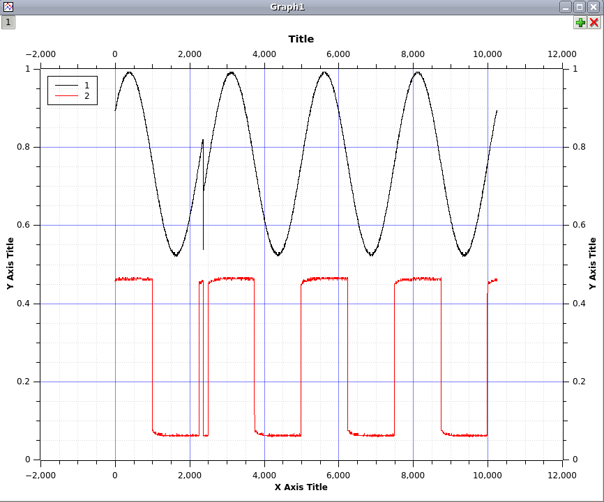
So why is the capture getting corrupted? Fortunately (courtesy of Bert Vermeulen), I have just the tool to find out: The OpenBench Logic Sniffer. This device is a logic analyser capable of sampling at up to 200MHz - fast enough to trace the ESLA201A while it samples.

Here I have attached 8 probes to the 8 data output lines of the ESLA201A's TLC5510I ADC, and a probe to the ADC clock input.

I then set the ESLA201A to sample continuously with sigrok-cli. I like to use cpipe to measure that the pipe throughput is what I would expect it to be, and then dump the data in /dev/null.

$ sigrok-cli --driver=fx2lafw --device samplerate=1M --continuous -O binary | cpipe -vt > /dev/null
thru: 1854.344ms at   69.0kB/s (  69.0kB/s avg)  128.0kB
thru: 132.646ms at  965.0kB/s ( 128.8kB/s avg)  256.0kB
thru: 127.458ms at 1004.3kB/s ( 181.6kB/s avg)  384.0kB
thru: 132.681ms at  964.7kB/s ( 227.8kB/s avg)  512.0kB
thru: 127.580ms at 1003.3kB/s ( 269.5kB/s avg)  640.0kB
thru: 132.563ms at  965.6kB/s ( 306.3kB/s avg)  768.0kB
thru: 132.689ms at  964.7kB/s ( 339.4kB/s avg)  896.0kB

...then I set PulseView to capture a trace:

So far this is what I would expect to see. Channel 0 is the clock input, and channels 1-8 are the data output, where channel 8 is the MSB. Therefore the ADC is reading a value of 127, which for a 0V input is correct.

So could this be an issue of timing? The TLC5510I has a minimum high and low clock pulse duration of 25ns. To find out, we will use PulseView's cursors feature.

Putting the cursors around the trough, we can measure a low-duration of 40ns. So no problem there. There are no other constraints on the timing signal - they don't have to be symmetrical pulses.

So I kept repeatedly clicking Run to see if things would always run so smoothly. Suddenly this happened...

Lulwat?

The ADC seems to be having some kind of spaz-attack. So far I haven't been able to figure out exactly what has caused this. However, there do occasionally seem to be problems with the clock signal:

If this logic analyser is seeing what the ADC is seeing, this would explain a lot about why the ADC has gone crazy. The question to determine whether this is a problem with the fx2lafw firmware, or whether there is some signal integrity problem - and what would cause that.

By way of comparison, I decided to see how the USBee software suite would fair on the same problem. So I fired up my trusty Windows XP VM. Interestingly, it too exhibited a very similar behaviour.

I hadn't done any logic analysis with the official firmware before, so I wasn't sure if it would show some mistake I had made in the shape of my clock pulse. In the end it showed a clock signal that was almost identical - except the low-pulses were 30ns rather than 40ns.

Conclusion

I suspect even if I figure out the cause of the corruption, the device will never be a very good oscilloscope, if it has these kinds of ground bounce effects. This is the decay you can see in the analog trace above, and if there are issues with the design either on the digital or analog side, there may not be much I can do about them.

Having said that, even if the board does have digital signalling issues, attaching lots of logic analyser wires to it will make them much worse, so some of the issues we are observing here may have been self induced.

Any suggestions would be welcome.

But anyway, this is all beside the point. PulseView managed to come through this experiment without crashing and delivered some interesting insights.

Releasing... everything

$
0
0

It's been a while since we last released a new version of libsigrok. A lot of work has gone into the library since then, but we somehow never got around to doing releases — there was always some major API change coming, or a driver that was nearly finished.

So here's a release now, and it's a good one. We're simultaneously releasing the following:

As announced earlier, libsigrok now supports analog sources, such as oscilloscopes. But this has actually led to many other classes of hardware as well, and we wrote tons of drivers. We've added support for the following:

Logic Analyzers

  • CWAV USBee DX
  • ZEROPLUS LAP-16128U

Oscilloscopes

  • Hantek DSO-2090
  • Rigol DS1052D, DS1052E, DS1102D, DS1102E

Multimeters

  • Agilent U1231A, U1232A, U1233A
  • Brymen BM857
  • Digitek DT4000ZC/TekPower TP4000ZC
  • Fluke 187, 189, 287, 289 and the Scopemeter 199B
  • Mastech MAS345
  • Metex ME-31, M-3640D
  • PCE PCE-DM32
  • PeakTech 3410, 4370
  • RadioShack 22-168, 22-805, 22-812
  • Tecpel DMM-8060, DMM-8061
  • UNI-T UT61D, UT61E
  • V&A VA18B
  • Victor 70C, 86C
  • Voltcraft VC-820, VC-840

Sound level meters

  • Colead SL-5868P
  • Tondaj SL-814

Temperature, humidity and CO loggers

  • Lascar EL-USB (various models)
  • MIC 98581, 98583

All of these devices have their own page in our wiki, with full teardowns and protocol documentation. You can find an overview here.

Existing drivers have seen many bugfixes and improvements as well: check the NEWS file for details. There are also input modules for the VCD and WAV file formats, and an output module that pretty-prints analog output with appropriate units.

The commandline client, sigrok-cli, has been updated to deal with the analog devices, and has had an overhaul of the commandline options; this should make it a bit more intuitive to use. Check the man page for details and some examples.

The python decoder library, libsigrokdecode, now exposes decoder options to clients. There is also a new decoder for the Dallas DS1307 RTC chip's protocol.

Up until now, sigrok-cli has been the only officially supported sigrok client. That's changing: we're happy to announce that PulseView is getting its first release as well, and will be officially supported from now on. That means releases of libsigrok and pulseview will be kept in sync, with respect to API/ABI compatibility. We also enforce this in the git development repository. When PulseView gets support for protocol decoding, we'll keep it in sync with libsigrokdecode as well.

All four releases are considered pretty stable; we don't know of anything that crashes at the moment. If you find a bug, please take the time to post a bug report.


Ikalogic SCANALOGIC-2 now supported

Two Sound Level Meters

$
0
0

We now have support for two more sound level meters in libsigrok. Both can do live streaming, and do standalone logging for later retrieval.

First is the CEM DT-8852, a large handheld unit. It has all the usual features you'd expect in a sound level meter, and claims IEC 61672-1 Class 2 compliance. Particularly interesting is the fact that it can stream its dB measurements to the host at 20Hz; this sort of device generally streams at 1 or 2Hz.

The firmware is somewhat... temperamental. It was a particular challenge getting the driver to control settings on the device. The vendor software typically takes between 0.1 and 10 seconds before changing a setting actually takes effect on the hardware. The sigrok driver does considerably better: it's reliably under 1.5 seconds, and usually much faster. It all works very well now: the sigrok driver has workarounds for all known bugs.

The second new SLM driver is for the Kecheng KC-330B. It has a "USB stick" form factor, and so is intended mostly for standalone logging. It doesn't work very well: logging can only be started manually, by pressing the button, and even then it's not so sure to actually work. The sigrok driver only supports streaming from this device for that reason: the data logging functionality on the device is just too unreliable.

libsigrok 0.2.1 released!

$
0
0

Hi everyone!

We're happy to announce the new libsigrok 0.2.1 release. This is mostly a bugfix release with a few additional new drivers to support more hardware. No major API changes were performed.

We added support for two new logic analyzers. One of them is the IKALOGIC Scanalogic-2, a 4-channel device with a max. samplerate of 20MHz. The driver was contributed by Marc Schink (thanks a lot!), who also wrote up some nice documentation about the USB HID based protocol in the wiki.

The other device we now support is also an IKALOGIC device (just a coincidence), namely the new ScanaPLUS, a 9-channel logic analyzer with a fixed samplerate of 100MHz, which compresses the captured data and streams it to the PC. This device uses an FPGA internally and an FTDI FT232H for data transfers. The protocol is thus not USB HID based like on the Scanalogic-2. We documented the ScanaPLUS USB protocol in the wiki too, if you want to have a look at the details.

We now also support two additional sound level meters, the CEM DT-8852 and the Kecheng KC-330B. Please check the previous blog post about these devices.

Finally, support for four new multimeters has been added, the UNI-T UT60A and UNI-T UT60E (thanks Florian Knodt!), the Voltcraft M-3650D (thanks Florian Steinhardt!) and the Voltcraft VC-830. They were all pretty easy to add to our generic 'serial-dmm' driver which can support a wide variety of serial-based DMMs with "simple" protocol.

Apart from that we added a few new config keys, config info types, and error codes. We also did the usual bunch of code cleanups, documentation improvements, and bugfixes. Please read the NEWS file for details.

You can download the libsigrok-0.2.1.tar.gz tarball from sigrok.org/download as usual.

Have fun!
 

Collecting measurements

$
0
0

The collectd project is the de facto standard setup for server statistics: it grabs all kinds of local statistics (network counters, disk I/O, etc) and logs it locally or to a remote collectd, say on a dedicated statistics machine. It's a very modular system: everything is in plugins, including input sources like SNMP and OneWire. The default output plugin is the venerable RRDtool. This stores values and averages them over time, and creates graphs on demand.

Collectd has just released version 5.4, now with a sigrok plugin. That means any device which can be accessed via libsigrok can feed information to collectd, for storage and graphing with RRDtool or any other output plugin. This is intended for the many analog devices supported in libsigrok, not the oscilloscopes and logic analyzers of course.

These graphs were made using a CEM DT-8852 sound level meter and UNI-T UT325 thermometer:


These show my clunky old air conditioning unit adding a whopping 19 dB(A) to the noise level, and the effect that has on the temperature. I also watched a very loud movie with lots of explosions in the evening! Here's the collectd configuration that generated the above:

LoadPlugin "sigrok"
<Plugin "sigrok">
    LogLevel 3
    <Device "Sound level">
        Driver "cem-dt-885x"
        conn "/dev/ttyUSB3"
        MinimumInterval 1
    </Device>
    <Device "Temperature">
        Driver "uni-t-ut32x"
        conn "1a86.e008"
        MinimumInterval 1
    </Device>
</Plugin>
What's obviously missing from the above is a measurement of the power usage of that air conditioning unit. I'm not sure I want to know...

Saleae Logic16 support

$
0
0

We're happy to announce that libsigrok now supports the Saleae Logic16 logic analyzer.

This is the successor product of the well-known Saleae Logic (an 8-channel logic analyzer with a max. samplerate of 24MHz and streaming capabilities).

The Logic16 has 16 channels and can sample at rates of up to 100MHz, depending on the number of channels used. If you only need 3 channels you can sample at 100MHz, or 50MHz for 6 channels, or 32MHz for 9 channels, or 16MHz when using all 16 channels.

The property of the Logic16 that makes it really interesting is that it can still stream out the data live over USB (like the Logic) and is thus not limited to any internal buffer size of the logic analyzer itself, while at the same time allowing a samplerate higher than 24MHz. This makes it possible to capture fast signals for longer periods of time (as opposed to just a few milliseconds as is the case for many other devices) which can be very useful in practice.

It also has the advantage that you can switch between two different voltage threshold settings, allowing you to debug either 1.8V / 3.3V systems, or 5V systems.

Of course it still has the same limitations as the Logic, too. Whether the continuous byte stream from the Logic16 can be received quickly enough over USB without missing any bytes depends on various random factors, such as the USB controller in your PC, the OS/kernel version used, the amount of other USB devices connected and how much data those transfer at the same time, etc. etc. But still, for many cases it works well enough to make it quite useful.

Many thanks to Marcus Comstedt for figuring out how the Logic16 protocol works, and for writing the libsigrok driver! He also documented the protocol in the wiki, as well as various firmware internals. We also have some teardown photos, pinouts of the ICs used in the Logic16 and their connections, EEPROM layout and other info in the wiki, if you're interested in this kind of stuff.

The device uses a Cypress FX2 USB chip and a Xilinx Spartan-3A XC3S200A FPGA internally. The first needs a firmware upload when the Logic16 is attached to USB, the latter needs an FPGA bitstream upload upon USB connection (as well as another bitstream upload whenever the voltage threshold setting is changed).

Thanks to Marcus Comstedt again who provided the sigrok-fwextract-saleae-logic16 tool which you can use to extract the FX2 firmware and the two FPGA bitstreams from the vendor software. See the manpage for details.
 

ISO-TECH IDM103N‎ multimeter support

$
0
0

Thanks to Aurelien Jacobs libsigrok now supports a new multimeter, the ISO-TECH IDM103N. This is a 4000 counts DMM with RS232 connectivity.

The respective patch for enabling this DMM also adds a generic es519xx.c parser (based on the old es51922.c which will be obsoleted soon), which should be able to handle various Cyrustek ES519xx DMM ICs. That'll make it easy to add more DMMs using one of these Cyrustek chips later.

Another new thing in libsigrok is the SR_UNIT_REVOLUTIONS_PER_MINUTE (RPM) unit, which allows us to properly support the DMM's RPM feature.
 

sigrok + UNIX = Awesome!

$
0
0

I've decided it's time to start blogging about the power of sigrok when used together with all the other tools on a typical UNIX machine. This sort of thing usually wouldn't be documented, because it's not really sigrok functionality, but for me these are the most powerful tricks of all.

Here's an example...

Example I - LogicPort BitBanging

Lee Jones has recently started working on a driver for the Intronix LogicPort. The original manufacturer has declined to provide any documentation about the protocol, so Lee has been working hard on reverse engineering it.

The LogicPort internally consists of a Altera EP1C4F324C6 FPGA, with a FTDI FT245BL USB interface.

For USB devices, our typical workflow is to run the vendor software inside a Windows VM and setup a USB passthrough. Then, in the Linux host machine we use usbmon (sometimes via Wireshark) to inspect the packets sent and received. To implement a driver, the developer must then try to replicate this protocol in the driver.

Lee discovered that early in the process of initialising the device, a large block of binary data is sent by the PC to the device. This is a hexadecimal dump of just the beginning part of the packet:

05070507 05070507 05070507 05070507 05070507 05070507 05070507 05070507
04060507 04060507 05070507 04060406 05070507 04060406 04060507 04060507
04060406 05070507 05070406 04060406 04060406 05070507 05070406 04060406
.... 

We suspected that this data is actually being used to cause the FTDI chip to bit-bang an SPI waveform to configure the FPGA. But how can we get more clarity? Answer: with sigrok.

  • First we need to convert this hexadecimal data to binary. xxd has a handy reverse mode that can input hex, and output binary:
    • xxd -r -p dump.txt > dump.bin
  • PulseView has basic support for importing binary data; currently it will assume any file ending in .bin is 8-probe logic data. Opening the file in PulseView, we can see the waveform clearly:
    PulseView now also has very basic support for protocol decoding, which allows us to see the bytes of SPI data.
     
  • Pretty though PulseView decoding is, sigrok-cli is actually more powerful in the end, because with sigrok-cli we can extract the actual bytes from the SPI data stream. Currently sigrok-cli has some problems with its binary input module (these are being addressed in bug #166), so this has to be done in two steps:
    • First, convert the binary data to a sigrok session file:
      • sigrok-cli -I binary:numprobes=2 -i dump.bin -o dump.sr
    • Second, do the decode from the session file:
      • sigrok-cli -i dump.sr -P spi:mosi=0:sck=1
      • Data is decoded:
        • spi: "FF/1FFE"
          spi: "FF/1FFE"
          spi: "5C/1FFE"
          .....
    • Finally we can use some UNIX magic to extract the firmware binary:
      • sigrok-cli -i dump.sr -P spi:mosi=0:sck=1 | cut -c7-8 | xxd -r -p > firmware.bin
      • (One day sigrok-cli will acquire a feature to decode directly into binary, but for now this pipeline works fine)

I think this stuff is really cool. I'm out of time for now, but I'll try and write up some more examples in following posts.

sigrok + UNIX = Awesome! - part II - Audio

$
0
0

So today I have another example of the powerful ways sigrok-cli can be used, this time with digital audio.

In the modern world there are a wide variety of devices that handle digital audio internally including HiFi equipment and mobile phones. Common signalling schemes include S/PDIF, and various clocked serial PCM schemes. I²S is a specific variant of PCM signalling. It has 3 signals: Clock, Word Select (which signals the beginning of sample words for the left or right channels), and Data which transmits the audio samples MSB first.

sigrok has had support for I²S decoding for a while, and now in the latest Git builds of PulseView, it's possible to see the decode results. This example was taken from the 32-bit I²S example in the sigrok-dumps repository.

But once again thanks to the power of UNIX, sigrok-cli is the far more powerful tool, because it allows us to do interesting things with the decoded information.

The basic syntax for I²S decoding is as follows:

$ sigrok-cli -i 2ch-16bit-16khz.sr -P i2s:sck=0:ws=1:sd=2 -A i2s=right

i2s: "Right channel: f6780000" "Right: f6780000" "R: f6780000" "R"
i2s: "Right channel: f4b80000" "Right: f4b80000" "R: f4b80000" "R"
i2s: "Right channel: f3ac0000" "Right: f3ac0000" "R: f3ac0000" "R"
i2s: "Right channel: f3060000" "Right: f3060000" "R: f3060000" "R"
    ....

Here 32-bit samples are being printed for the right channel only. In itself this is very cool, but we can go much further.

The next step is to extract the data as binary.

sigrok-cli -i 2ch-16bit-16khz.sr -P i2s:sck=0:ws=1:sd=2 -A i2s=right | \
    cut -c22-25 | xxd -r -p > file.bin

The cut command strips all the text except for the 4 most significant hexadecimal nibbles, and in the same way as in the previous blog posting, we use xxd's reverse mode to convert this hexadecimal data to binary.

We now have a binary dump of the PCM data for the channel.

But I want more.

The SoX suite has some really handy tools for manipulating audio, and we can use these tools to convert the audio to a WAV file.

sigrok-cli -i 2ch-16bit-16khz.sr -P i2s:sck=0:ws=1:sd=2 -A i2s=right | \
    cut -c22-25 | xxd -r -p | \
    sox -t raw -B -b 16 -c 1 -e signed-integer -r 16k - right.wav

Here we tell sox that it will receive a raw data stream, containing big endian, 16-bit, signed integer mono audio at 16kHz sample rate, and that it should output the data to a wav file.

Opening the wav file in Audacity, we can see the decoded analog waveform:

...or we can use the sox play tool to play the audio directly out of the headphones:

sigrok-cli -i 2ch-16bit-16khz.sr -P i2s:sck=0:ws=1:sd=2 -A i2s=right | \
    cut -c22-25 | xxd -r -p | \
    play -t raw -B -b 16 -c 1 -e signed-integer -r 16k -

I've never had the chance to try it, but I really want to see if it's possible to do this in real time on a live device.

At this time, it will be a tall order to ask this of libsigrokdecode, but it may nonetheless be possible. It would require a logic analyser capable of continuous streaming, such as the FX2 family of devices, and the I²S logic data would need to be acquired at the lowest possible sample rate without aliasing. If the logic data is captured at a higher sample rate, libsigrokdecode stands no chance of processing all of it.

There is some talk of various ways we can make great increases to libsigrokdecode's performance, so in the future this type of realtime activity should be rather easier to do.

sigrok at ELCE

$
0
0

The first conference presentation on sigrok is long overdue, but it's finally happening: Matt Ranostay is giving a talk at ELCE in Edinburgh, October 24-25. He will be giving an overview of the current state of the project. Thanks, Matt!

Quite a few sigrok developers will be at ELCE, and so we're also going to have a technical showcase stand, where we hope to demonstrate, among other things, PulseView's new integration with libsigrokdecode. If you're around, do drop by and say hello!

We'll also have a developer meetup, of course. We always have lots of designs in the planning stages, and getting together really helps to hash out the details. If you want to learn more about the internals of sigrok, or just have a say on where you want things to go, you're welcome to join us.

Viewing all 213 articles
Browse latest View live


Latest Images